Table of Contents
Placing and Handling of Fabric Formed Concrete
Depth of Bleeding Effect
Mix water bleeding through the fabric pores is the major cause affecting concrete quality cast in fabric or permeable formworks. Investigations on permeable formwork liners have shown that the effect of bleeding is limited only to a few tens of millimetres of the surface of the concrete [1]. In the present study, fabric formed concrete cylinders were cast with diameters varying from 100 mm in increments of 50 mm, to 250 mm to study if there was any change in cement or fine aggregate concentration close to the surface of the specimens in order to study the depth of the fabric formwork’s effect on the concrete as a function of diameter of the cylinders.
Molds were first made and cylinders were cast using a 30 MPa normal concrete. Hardened samples were all vertically cut in half, polished and sections of the specimens were studied visually and using a microscope. In all sizes, no visual concentration of cement/fine aggregates was seen and all sections had the same texture throughout. The presence of sectional large aggregates in the visual field made visual determination difficult. No relationship between the size of the cylinder and the bleeding depth could be determined in this test.
Fabrication of Fabric Molds
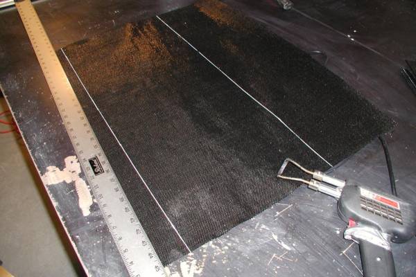
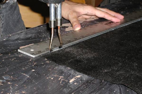
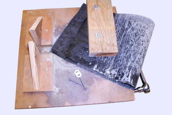
A simple formwork was designed and built to form concrete cylinders using fabric. In order to do so, the fabric needed to be cut to size. Woven geotextiles can be cut using scissors or a knife edge though edge fraying may occur. To avoid edge frying, fabric pieces were cut using a soldering gun. A blade-shaped tip and an aluminum straight edge were used to be able to follow straight lines when cutting (Figure 17 and Figure 18). By using a soldering gun to cut the fabric by melting, the fraying problem was completely avoided and sharp, straight edges were provided for the fabric samples. Cut fabrics were then sandwiched and bolted between two pieces of plywood. Plywood pieces were made wide enough to support and hold the fabric in between and resist the possible tension created in the fabric mold due to the hoop pressure created by the fresh concrete.
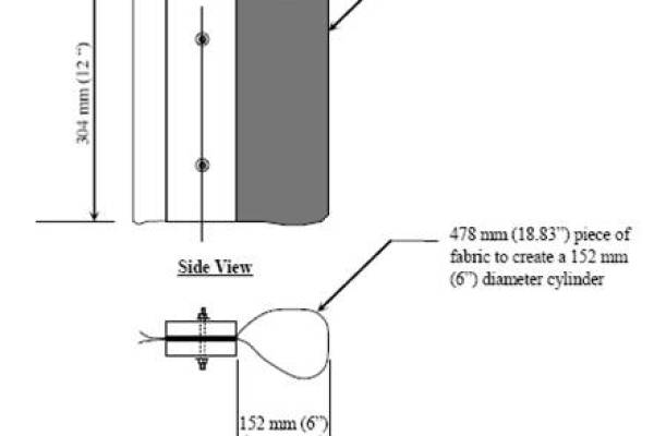
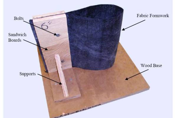
The height of the cut fabric and the plywood pieces were the same as the height of the desired 305 mm (12 in.) concrete cylinder (Figure 19). The length of the fabric piece was also measured to have enough room in between the plywood pieces and to create the necessary diameter for the hardened concrete cylinder. A wood base and two supports were also added to the forms to avoid possible movements of the mold during the casting (Figure 20).
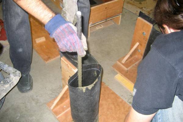
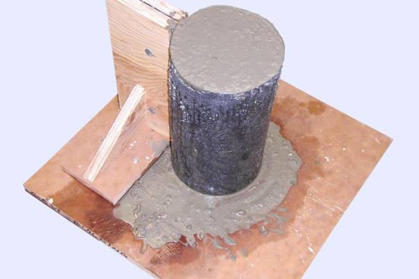
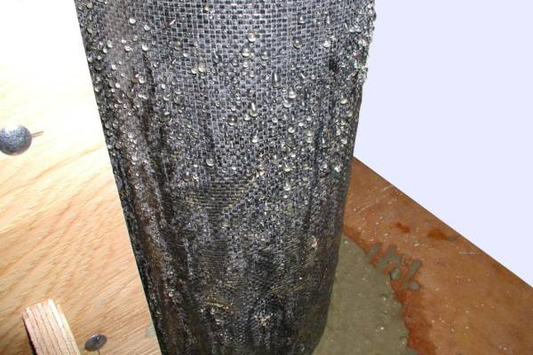
The bottom of the fabric forms could be left free as is done in commercial applications of the fabric-formed column molds [2]. The bottom of the fabric mold need only be held by hand when the first scoop of fresh concrete is placed inside the mold, after which the rest of the concrete can be poured in with no problem. Tapping the walls of the fabric formwork acts as vibration and helps start the bleeding of the air bubbles and water from the concrete. In order to comply with the existing cylinder casting standard [3], when pouring, samples were compacted in three layers using the standard compacting rod (Figure 21). Although an empty fabric form does not have any specific shape, the hydrostatic pressure created by the fresh concrete forms a perfect cylinder once it is poured inside the fabric mold (Figure 22). Figure 23 shows the bleed water within the first 45 minutes after casting.
<
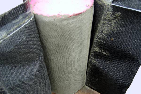
fs medium>When it was time for specimens to be taken out of their molds, the bolts were removed. Since polyethylene and polypropylene fabrics do not create any adhesion between the fabric and hardened concrete, there is no need for releasing oils and the fabric could be easily stripped off from the surface of the hardened concrete (Figure 24 and Figure 25).</fs>
Bleeding Tests
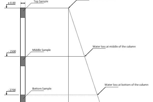
The relationship between bled volume of water and height in a concrete column was studied to see the effect of position along the height of the column on the amount of bleeding. It could be hypothesized that the amount of bleeding along the height of a fabric formed column varies as a function of location along the column’s height (Figure 26). In order to establish this relationship, pressure applied to the bottom and middle of the columns due to self-weight of normal density concrete was simulated by using a mechanical press.
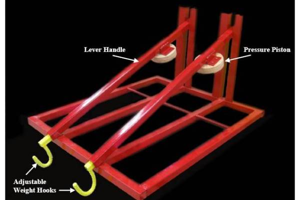
The mechanical press apparatus was designed and fabricated in the laboratory and calculations shown in Appendix B were made to find the load necessary to simulate the pressure at various heights along a 3 meters tall column’s length and apply it to both PVC and fabric formed specimens using an adjustable lever handle. HSS 38 by 38 mm steel square and L shape profiles were used to build the apparatus. As shown in Figure 27, each mechanical press apparatus was designed to have two handles in order to pressurize two cylinders at the same time.
A set of 54 samples of 152 by 305 mm (6 by 12 in.) were made and tested to investigate an assumed linear relationship between height of a column and the bleeding ratio. This series of samples (Table 6) were cast and the bleeding water was measured to find if the bleeding ratio along the height of a column.
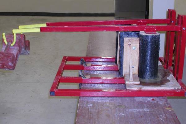
The variables in this test were fabrics Geotex 104F and 315ST in both pressured and unpressured molds, 30 MPa concrete with and without flyash (Type C) and plastic (PVC) molded samples as control specimens in pressured and unpressured molds. Fresh concrete was first poured and compacted into the fabric and PVC (control) molds. Lever handles were then slowly brought down and wooden pistons were adjusted over the top of the fresh concrete sample. A circular plastic sheet was cut and put in between the concrete and the piston in order to block any possible water absorption by the wooden pistons and to ease the release of the piston from the hardened concrete. Calculated weights were gently hung on the adjusted hooks (Figure 28) and bleeding water collection started immediately afterwards.
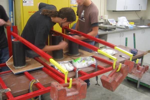
Bled water was carefully and constantly collected using absorbent paper sheets, as shown in Figure 29. These wet papers were kept in plastic bags in order to avoid water evaporation during the test. Following the test plastic bags were weighed full and empty and values were recorded. Paper sheets were then dried in the oven of 24 hours at 50°C and then weighed to find the amount of the water bled from each specimen.
Generally, bleeding liquid from the fabric formwork was thick and cloudy for the first few minutes and then it became very clear. The heavier loads initiated the bleeding process sooner. When higher pressures were applied to the specimens, bleeding volume was larger but the bleeding time was shorter.
Test Results
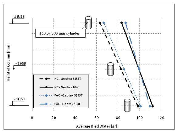
Figure 30 shows the relationship between the height of the column and the amount of water bled through the fabric. The results show linear relationship between pressure that corresponds to a point at specific height of a column and bled water. Geotex 104F which was the more porous fabric (see Table 2 and 3) led to a higher water loss. Greater bleeding causes a greater reduction in the water cement ratio and therefore the potential for in-creased compressive strength in the concrete. 152 by 305 mm (6 by 12 in.) cylinders were tested following the existing [ASTM] standard [3].
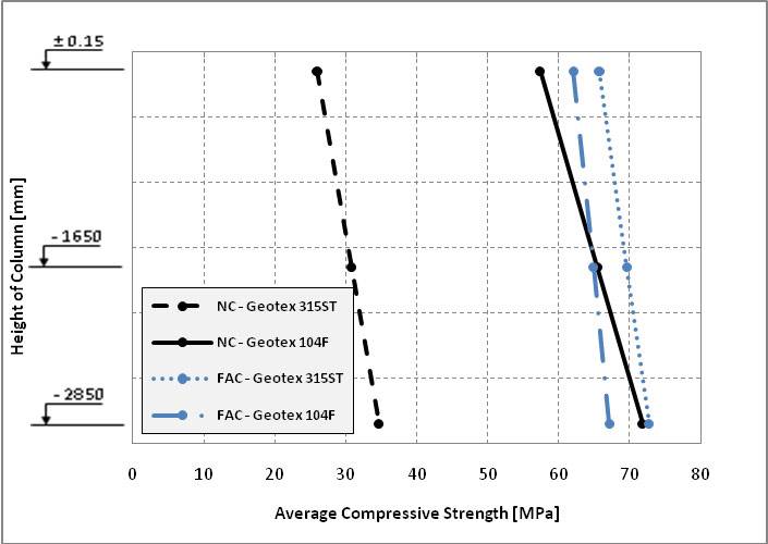
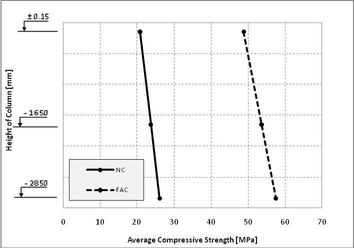
Compared to normal concrete, using the bottom-point cylinders, flyash concrete gained more strength than the normal concrete in both fabrics. When normal concrete was used, again, comparing bottom-point cylinders, Geotex 104F gained about 110% extra strength compared to the samples formed by Geotex 315ST. As for flyash concrete in the bottom-point cylinders, fabrics behaved the opposite way, Geotex 315ST gained about 7% extra strength than 104F. As seen in Figure 31, the concrete strength also increases linearly from top to bottom of column. It is important to note that this linear relationship between strength gains towards the bottom of concrete column is not limited to fabric-formed concrete. Similar results were found by Maynard and Davis [4] and in this study that used PVC molds (Figure 32). This increase in compressive strength is due to due to self weight of the fresh concrete and extra compaction at the bottom of all conventionally and fabric formed columns and due to higher density concrete formed in that section.
Finish Effect of Vibration on Concrete Surface
In another test, the change in quality of the surface due to vibration was also studied. A series of six 152 mm (6 in.) by 305 mm (12 in.) cylinders were made by Geotex 315ST and Geotex 104F. Molds were cast using a commercial flyash concrete (Lafarge, with 125 mm of slump), following the Canadian code requirements [5]. Samples were vibrated for about eight seconds using an electric concrete internal vibrator. Fabric formworks were removed after 24 hours. The less porous fabric Geotex 315ST produced a much better surface finish due to less fine aggregates and cement bleeding through the fabric pores. Geotex 104F, on the other hand, did not provide a uniform texture and created some color variation on the surface which may have been due to excessive fine aggregate escape from the surface of the fabric mold. Bleeding water from Geotex 104F was cloudier than that produced by Geotex 315ST, indicating a greater concentration of fine particles through the fabric’s pores. Based on this test, if a concrete surface finish is required, Geotex 315ST is recommended.
See Also
Place text here.
References
[1] Malone, Philip G. Use of Permeable Formwork in Placing and Curing Concrete. Vicksburg: U.S. Army Engineer Research and Development Center, 1999.
[2] Fab-Form Industries Ltd. 2009. http://fab-form.com/ (accessed August 11, 2009).
[3] ASTM C39/C39M-04a, ASTM. “Standard Test Method for Compressive Strength of Cylindrical Concrete Specimens.” In Annual Book of ASTM Standards, by ASTM, Vol. 04.02, 18-22. Easton: ASTM, 2004.
[4] Maynard, D. P., and Davis, S. G. “The Strength of In-situ Concrete.” The Structural Engineer, 1974: Vol. 52, 369-374.
[5] Kosmatka, Steven H., Panarese, William C., Gissing, Kathaleen D., and MacLeod, Norman F. Design and Control of Concrete Mixtures. Ottawa: CPCA, 1995.
External Links
Place text here.
